
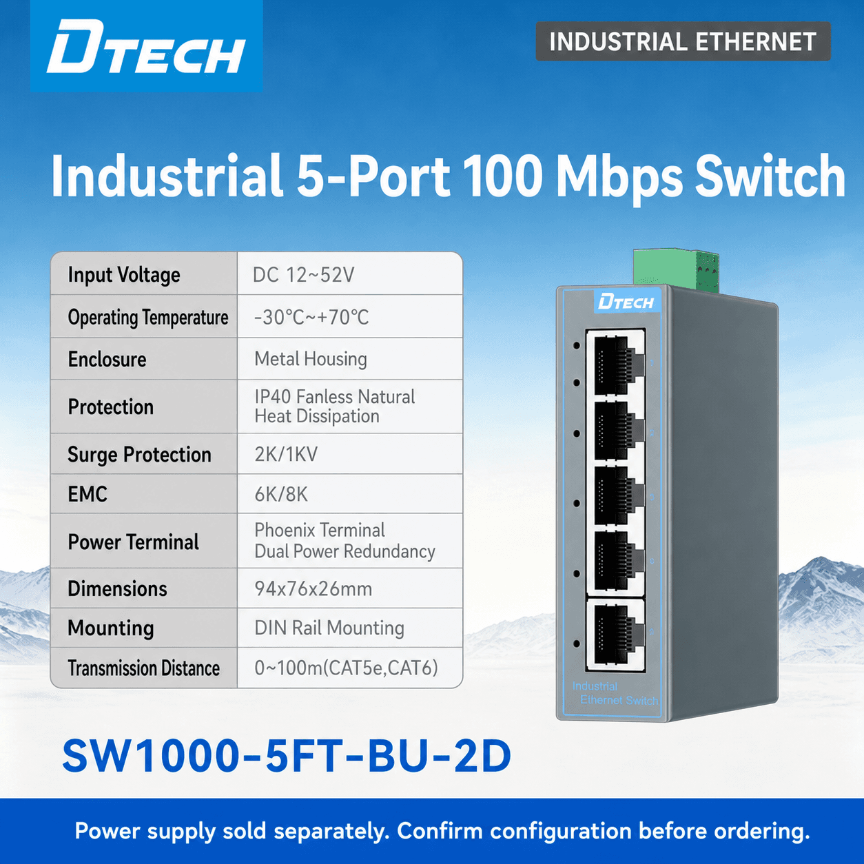
Why industrial Ethernet is the network foundation
Industrial Ethernet switches provide structured connection points between compatible PLCs, HMIs, industrial PCs, cameras, controllers and gateway devices. In a cabinet or distributed automation layout, switching is the layer that turns individual Ethernet connections into a documented and maintainable local network.
Selection should begin with the topology, not the product label. Record every endpoint, expected uplink, required media type, power source, physical installation location and service responsibility. This lets the engineering team distinguish a local access switch from a backbone, a PoE access point or a managed network node.
Managed, unmanaged, PoE and fiber choices
An unmanaged switch can suit a straightforward, fixed connection role where the project does not require configuration or network visibility. A managed switch may be appropriate when the project requires agreed configuration, diagnostics, segmentation or topology control. The exact software functions and supported protocols must always be checked against the selected model documentation.
PoE can simplify a compatible powered-endpoint deployment, while fiber media or fiber ports can be relevant for longer transmission paths or electromagnetic considerations. These are not universal requirements: cable type, distance, power budget, device compatibility and installation rules determine the final design.
Commission with a maintainable port plan
A well-prepared installation includes a cabinet drawing, port schedule, endpoint names, uplink record and a clear owner for IP addressing and configuration. Test the local endpoints before the upstream route, then validate the target application. This sequence reduces time spent searching for cable, address or application-layer issues.
For delivery, agree inspection items such as model, quantity, visible condition, requested basic functions, labels, accessories and packaging. Keep records proportional to the agreed scope and do not represent a product-level inspection as a complete network acceptance test.
Recommended visuals
Show the connection path with real, approved evidence.
Hero image: Use a real application, cabinet or product image that shows the field environment and leaves space for the page headline.
Engineering image: Place an approved control-cabinet, installation-preparation or factory-test image after the architecture section. Caption it with the actual process shown.
Delivery image: Where available, use a real shipment-inspection or packaging image. Do not use AI imagery as evidence of a completed customer project, factory audit or certification.
Conclusion
Make the connectivity decision from the actual project conditions.
Build a structured industrial network for PLCs, industrial PCs, cameras, controllers and IIoT equipment. A clear equipment list, network path and installation record give the project team a more dependable basis for selection, testing and support than a generic product list alone.